Raspberry Pi Software installation
These instructions are done as a “log file” of a succesful installation. You may tailor them in order to be useful for your concrete PC OS, SD Card size, etc...
We can find this installation photo log in: https://www.flickr.com/photos/txinto/sets/72157645597048656/
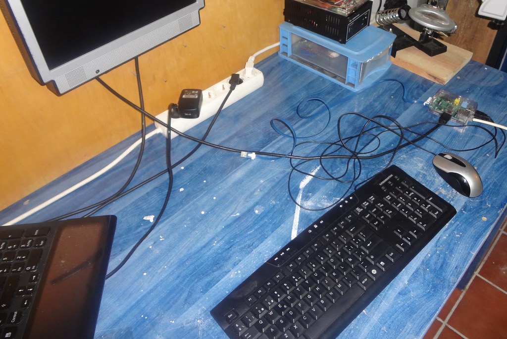
The equipment used for this installation was:
- A linux laptop with Fedora 20.
- A Raspberry Pi.
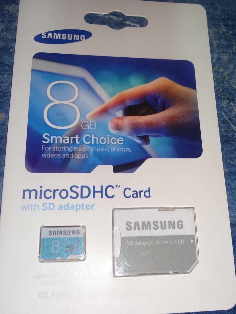
- An 8Gb SD Card.
- An ethernet lan with internet access.
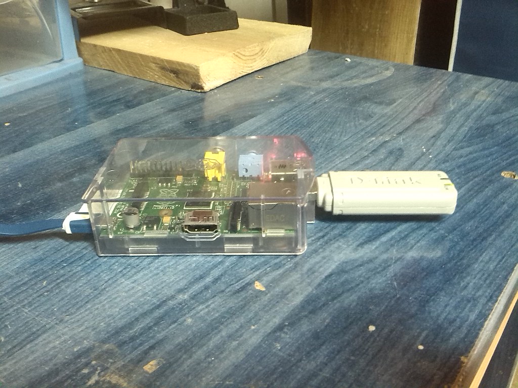
- A Wifi D-Link USB Key.
- A wifi lan.
- A monitor with HDMI.
- An USB keyboard.
- An USB mouse.
- An externally powered USB hub, as we will need more power for devices like the USB Wifi Key).
In this process we will install into a Raspberry Pi the following software:
- Latest Raspbian.
- Arduino tools.
And we will configure the following mechanisms:
- A boot script that sends an e-mail to communicate the Raspberry Pi IP.
And the following device:
- A wifi D-Link USB key.
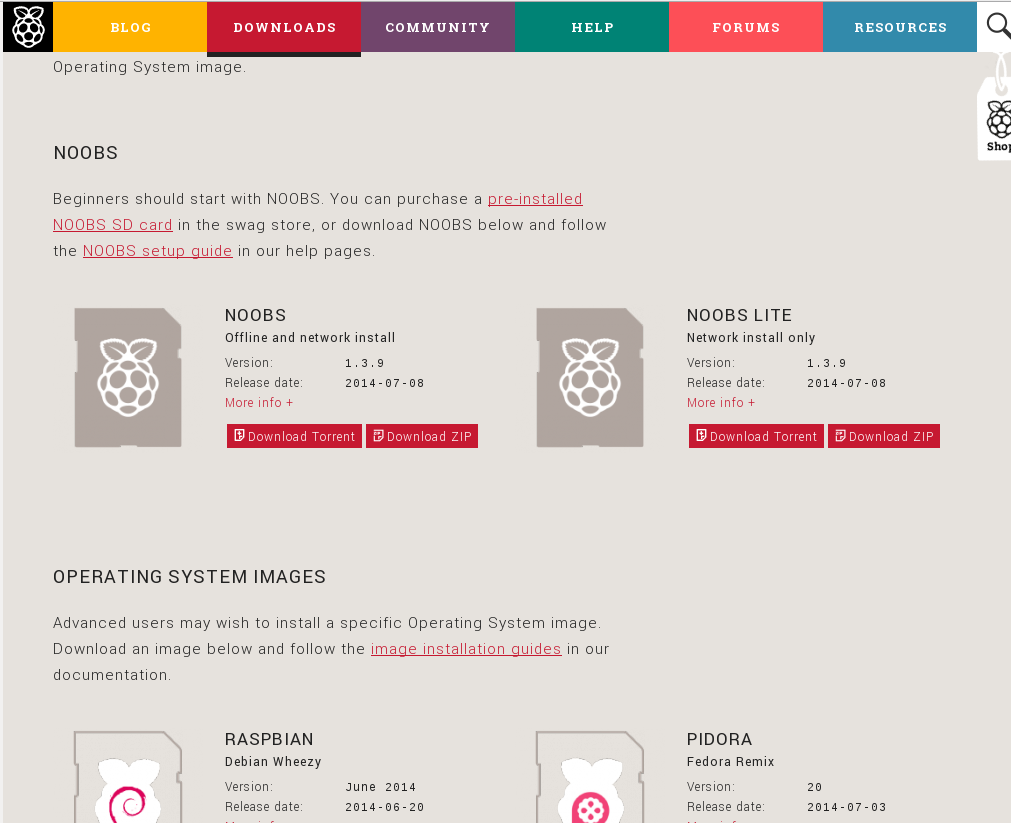
Preparing the SD card with NOOBS
First, we download the NOOBS lite from here:
http://www.raspberrypi.org/downloads/
We open the ZIP file and see INSTRUCTIONS-README.txt file for instructions.
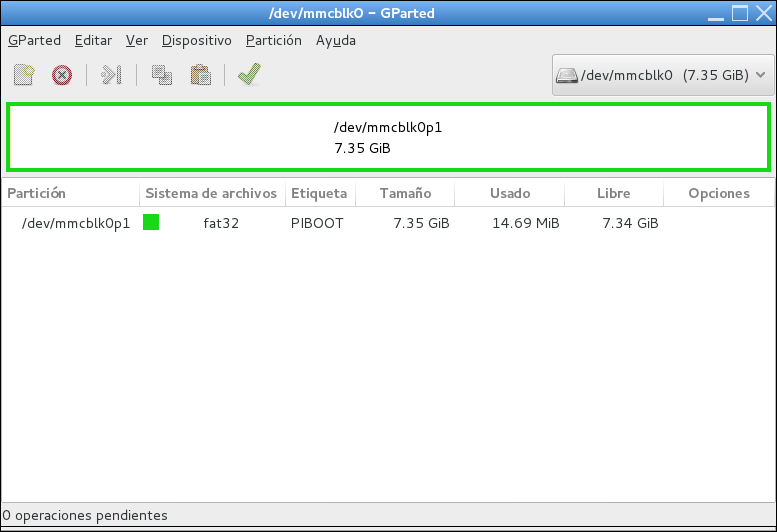
We format using GParted the entire unit:
- Open GParted.
- Select unit.
- Unmount it.
- Select existing partitions.
- Erase it.
- Apply all the changes.
- Create new partition.
- Assign all the available space to it.
- Select fat32.
- Select “Primary partition”.
- Name it as you want (here “PiBoot”).
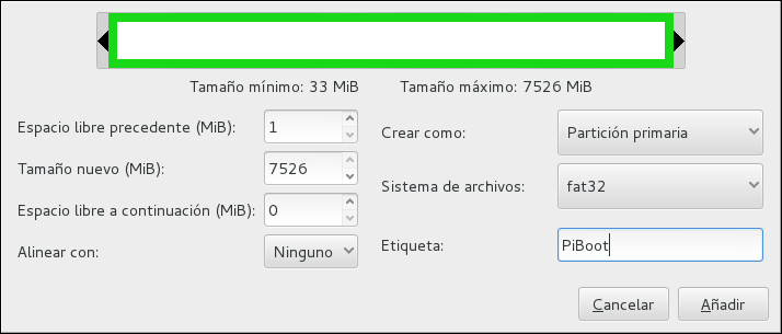
- Press create.
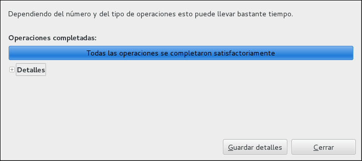
- Apply all the changes.
- Close GParted.
We mount the PIBOOT unit using the file manager of our system, and copy the contents of the ZIP file in the SD card. After that, we unmount and eject the SD card from our computer.
Raspberry Pi’s first boot.
NOTE: We will call RPi to the “Raspberry Pi”
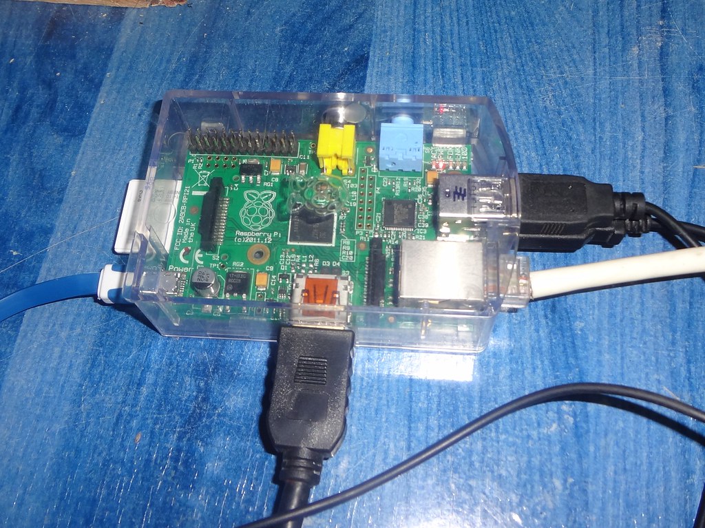
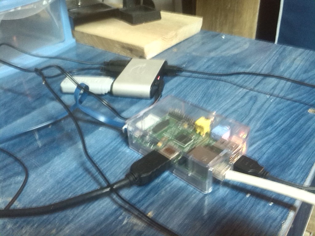
- We introduce the PIBOOT SD Card into the RPi.
- We connect the USB Keyboard and mouse to the RPi USB ports.
- We connect the HDMI monitor to the HDMI connector of the RPi.
- We connect the ethernet lan to the RPi ethernet connector.
- Finally, we connect the power supply of the RPi to it, and turn on the HDMI screen.
After few moments, we are asked about what OS to install.
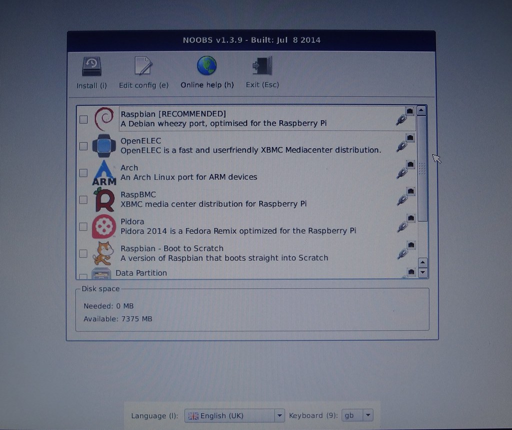
- We select Raspbian, and (in our case) select English (UK) language and spanish keyboard (es) distribution.
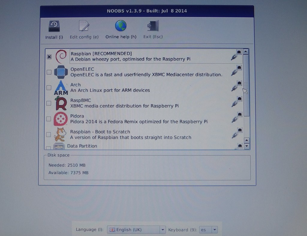
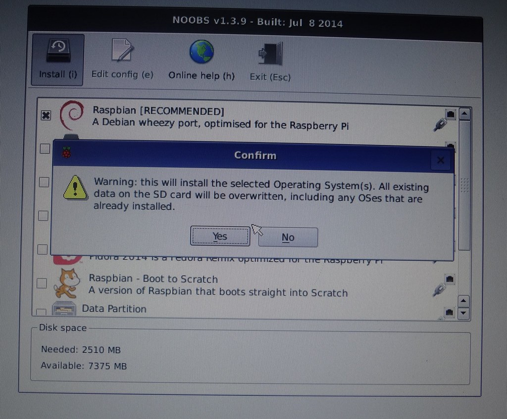
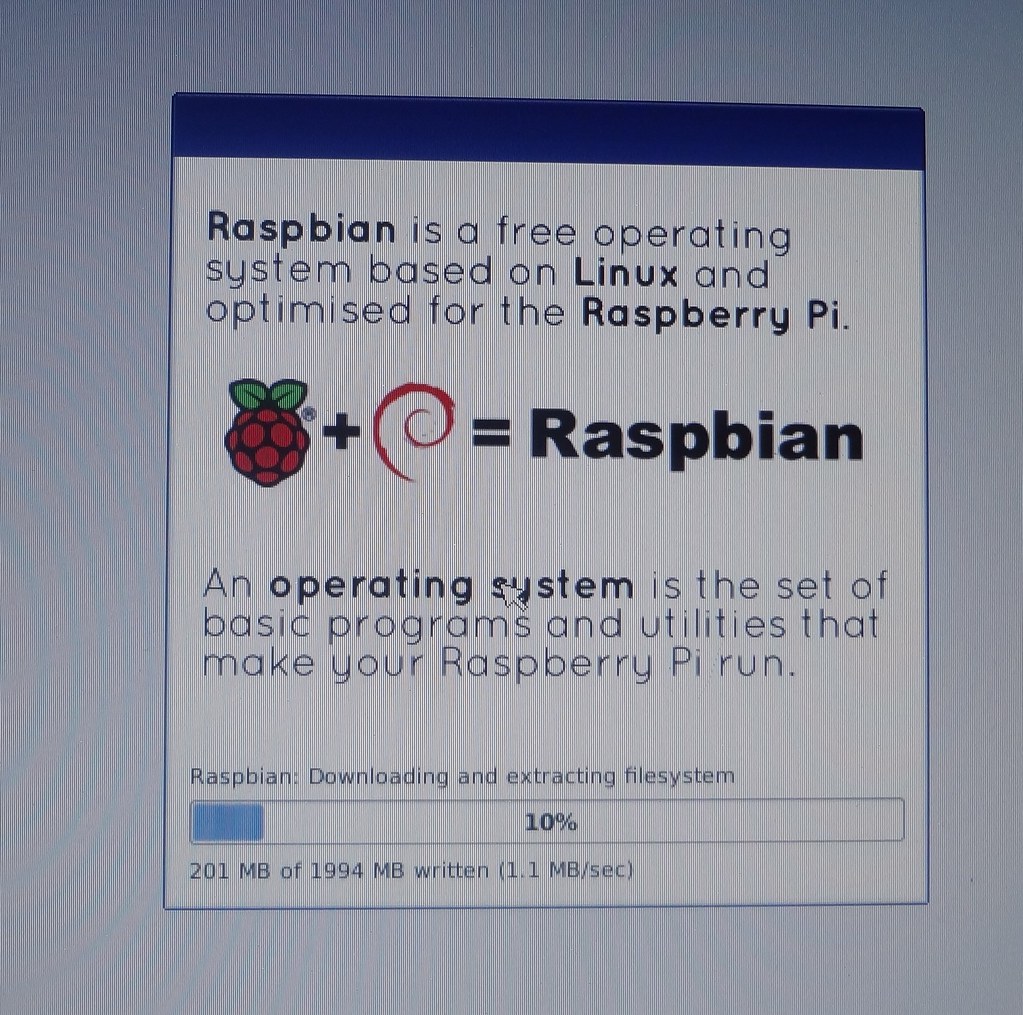
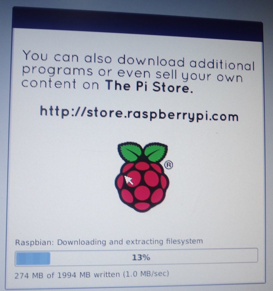
- We press the Install button and wait until the process is finished. RPi will use ethernet lan connection to access to the internet and download Raspbian and install it into the SD card.
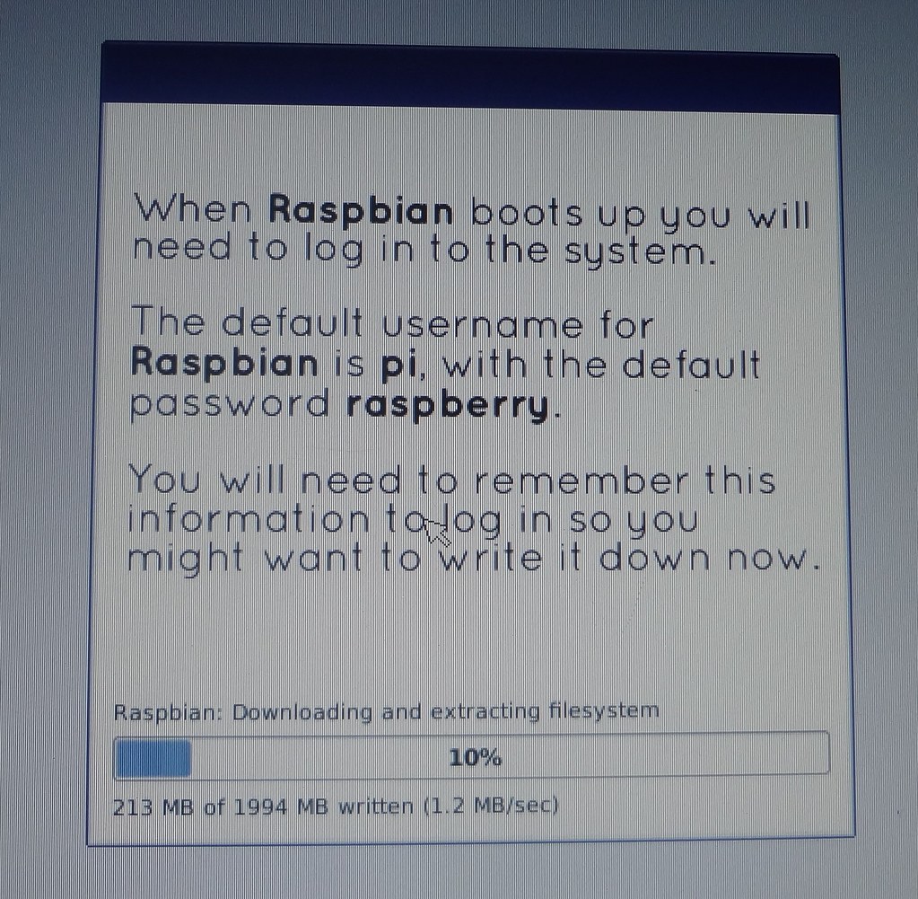
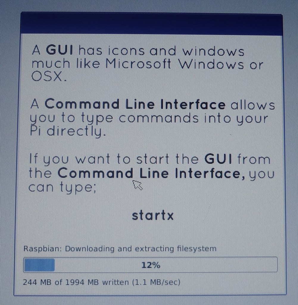
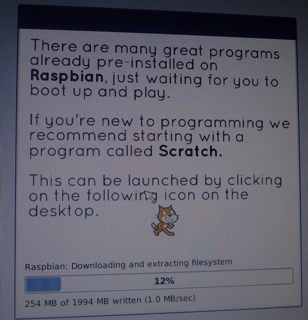
- During the process we can read some advices and hints about how to configure the Raspbian, interesting tools, how to start the graphical environtment, etc...
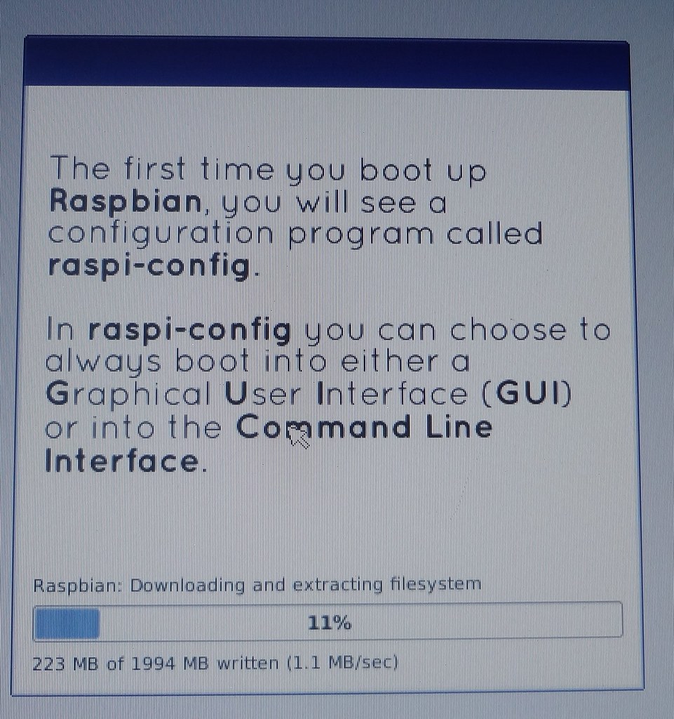
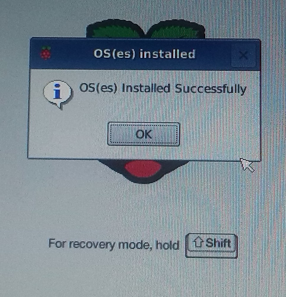
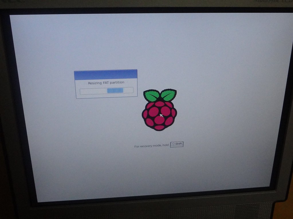
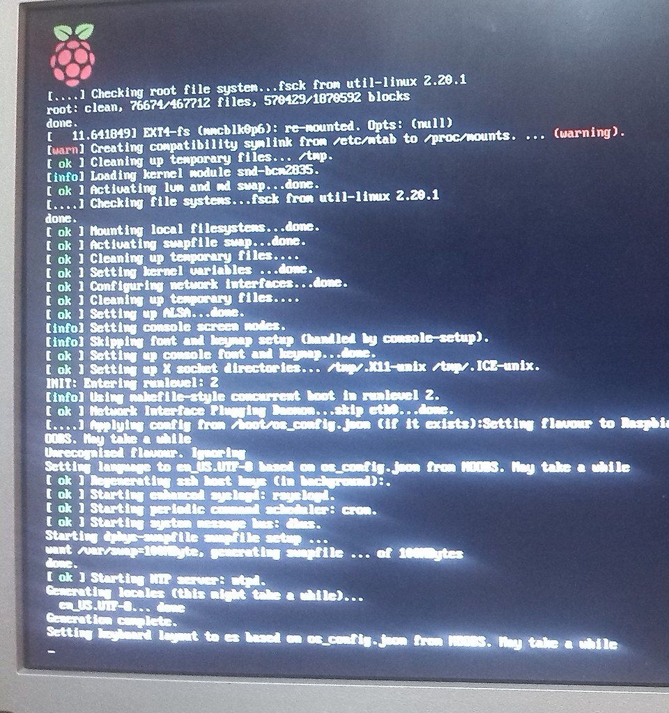
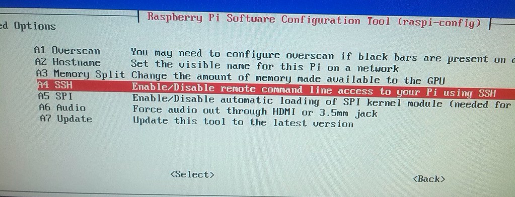
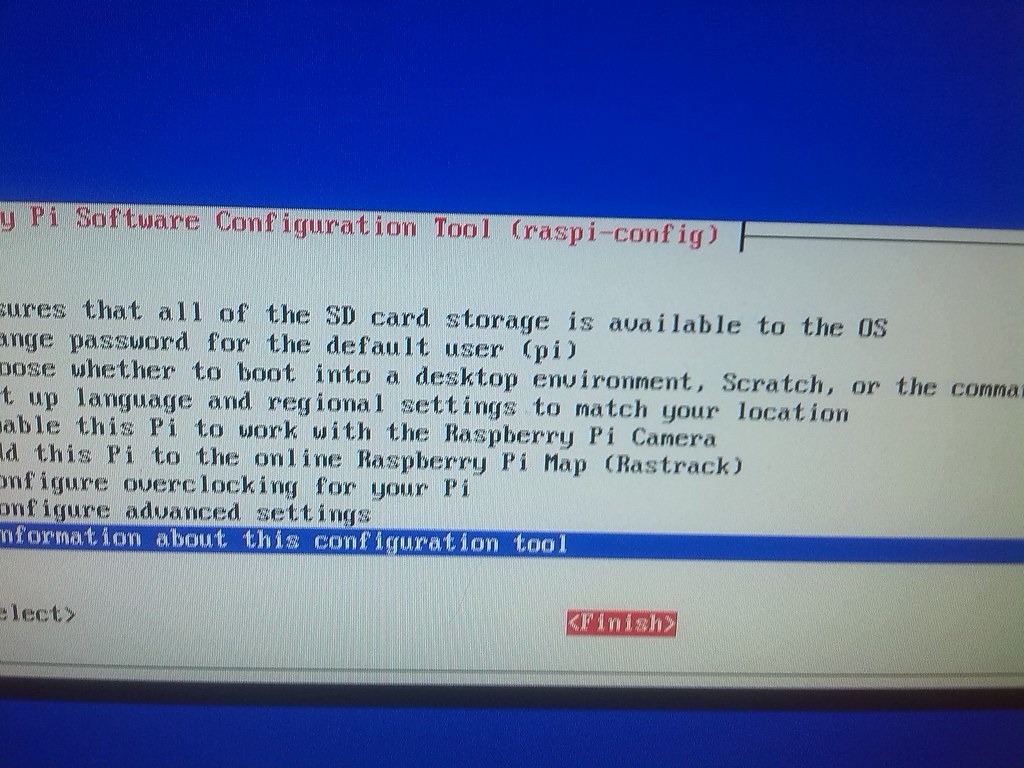
After several minutes, the OS is downloaded and installed, and the RPi boots from the Rasbian OS and automatically executes 'raspi-config’. We will proceed to make some configuration:
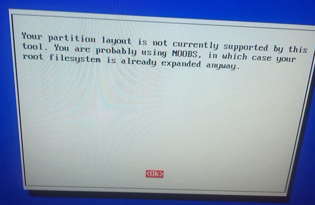
- First, resize the partition to use the 8Gb card. This is normally needed because you can have a different size SD Card and the Raspbian OS image can have been done using another size. But, in our case, this step is not needed because we are not installing Raspbian directly from a Raspbian image.
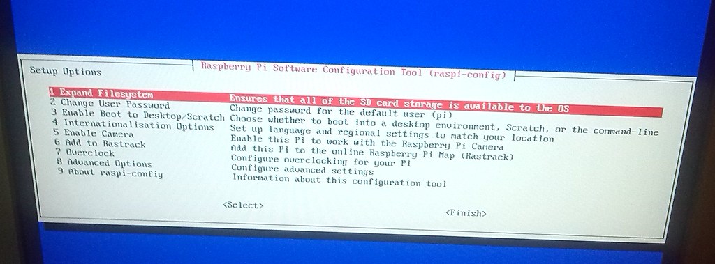
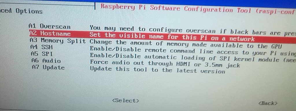
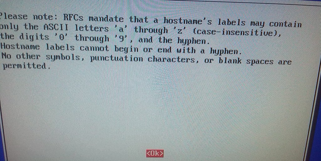
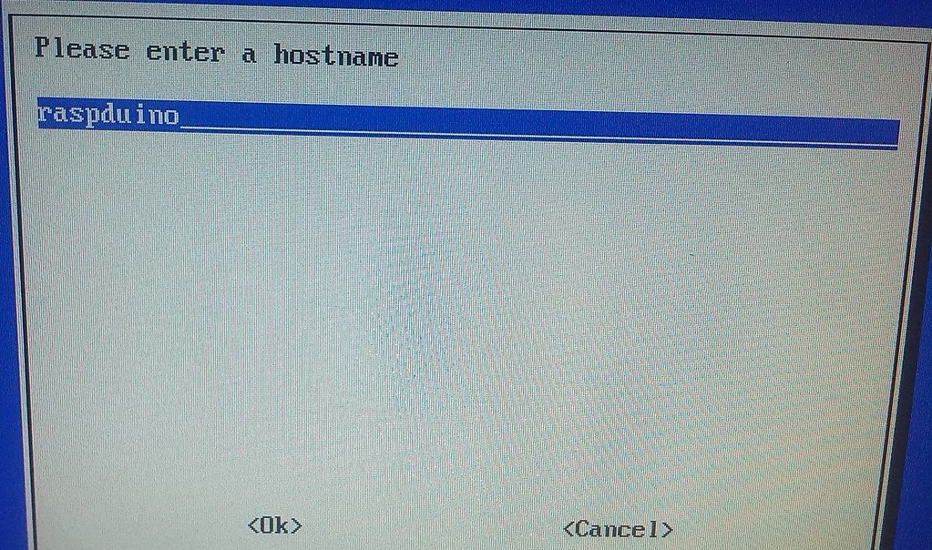
- Then, we will change the RPi hostname, in order to make it different from other RPis. It is recommended to put a different hostname for each RPi in your lan scope, to make it easier to identify which one are you connecting to, when, in the future, you will use SSH to reach them.
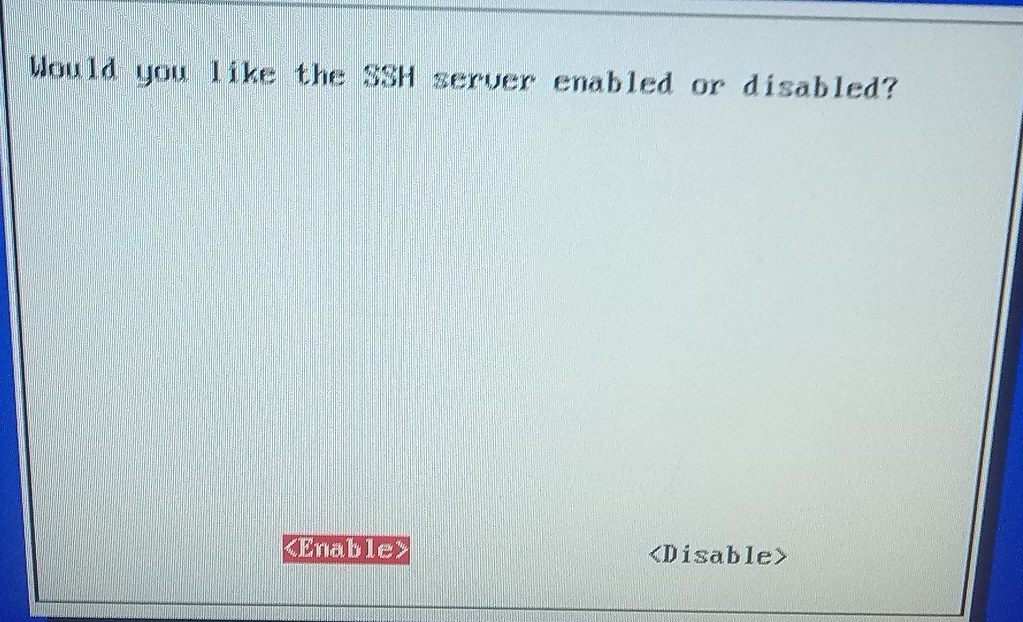
- After that, we will enable the SSH connection, so we can use just an SSH connection to manage the RPi, and we can stop needing the monitor, keyboard and mouse.
Once this configuration is done, we can close 'raspi-config’ and execute 'sudo halt’ to stop the system.
Configuring the system to send an e-mail informing about the IP.
We start the RPi again, after some time the system is asking us for login:
- User: pi
- Password: raspberry
We recommend to not change this login user password until the system is totally configured.
To make easier to continue, we will manually investigate the RPi IP and then connect remotely from the laptop using SSH. In the RPi console we will execute the next command:
ifconfig
And annotate the IP (in this case we got 192.168.1.24). Then, from the laptop computer we can connect to the RPi using:
ssh -X pi@192.168.1.24
NOTE: -X option activates the X-Windows tunnelling, and this will be useful later when configuring the Wifi connection of the RPi and also when working with the Arduino IDE.
Before installing software, we recommend to update the RPi software packages to their latest version:
sudo apt-get update
We will use the Git utils for downloading latest stable software for RaspDuino, and we will use some files in that software to perform the configuration, so first thing we will need is to install git tools.
In fact, git tools are already installed in Raspbian, but if not you can use:
sudo apt-get install git
Now we will create the raspduino folder and clone inside it the last version of the software. We will use the instructions found here:
http://stackoverflow.com/questions/24085978/github-url-for-latest-release-of-the-download-file?lq=1
mkdir raspduino
cd raspduino/
git clone https://github.com/txinto/gatArduinOSEK .
git fetch --tags
latestTag=$(git describe --tags `git rev-list --tags --max-count=1`)
git checkout $latestTag
Now we are in
/home/pi/raspduinofolder and we have the last stable release for the RaspDuino software.
Please take into account that te Arduino IDE needs the libraries to be present in the ~/sketchbook directory, so we will need to do this symbolic link to be able to later compile Arduino software:
cd ~
ln -s ./raspduino sketchbook
NOTE: The strategy to receive the IP address of the RPi on every boot is taken from this web: http://elinux.org/RPi_Email_IP_On_Boot_Debian
In the ~/sketchbook/gatArduinOSEKsample/rpi_i2c_master folder there is an script that allows the RPi to send the IP through e-mail. As this file is an example and it is under version control, we will copy it to a folder in another folder in order to taylor it for our needs.
cd ~
mkdir utils
cd utils
cp ../sketchbook/gatArduinOSEKsample/rpi_i2c_master/startup_mailer.py .
This script is prepared to use a well configured GMail account. Taylor it for your needs, probably you will need to investigate further if you are not using GMail as the sender email account. To do it, you can use the already incorporated 'nano’ editor (or use your favourite one, installing it previously).
nano startup_mailer.py
Once you are done, you can test if the e-mailer is working using the python interpreter:
python startup_mailer.py
If no errors, check the destination e-mail account to see if an e-mail has been received.
Now we will introduce the script in the rc.local file:
sudo nano /etc/rc.local
#
# By default this script does nothing.

# Print the IP address
_IP=$(hostname -I) || true
if [ "$_IP" ]; then
  printf "My IP address is %s\n" "$_IP"
  python /home/pi/utils/startup_mailer.py
fi

exit 0
Take into account that we have only added this line to the file:
python /home/pi/utils/startup_mailer.py
Now you can test it:
- '
sudo shutdown -r now' from the SSH console in the laptop. - The SSH console will be closed.
- Check e-mail for the IP sent by the RPi (probably will be the same).
- Connect again using the SSH command used before.
Configuring the Wifi lan connection.
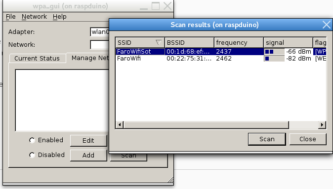
We will use the 'wpa_gui' tool for configuring the Wifi USB Key in the RPi.
- 'sudo halt' to stop the RPi.
- The SSH console will be disconnected.
- Unplug RPi power supply.
- Disconnect the USB Keyboard and USB Mouse.
- Plug the externally powered USB hub to one of the RPi USB ports.
- Plug the USB Keyboard, mouse and Wifi Key to the USB Hub.
- Power on the USB hub
NOTE: please take into account that when you power on the USB hub, it probably will cause RPi to be powered on. If this happens, the next step can be omitted. But you might also know that one of the USB hubs that did this strange thing was also causing the ethernet and USB ports to be useless. - Power on the RPi.
- Check the e-mail to know the new IP for the RPi (probably will be the same).
- Use SSH on the laptop to connect to the RPi (don’t forget using the -X option).
Once logged in, execute 'wpa_gui’ to configure the Wifi network.
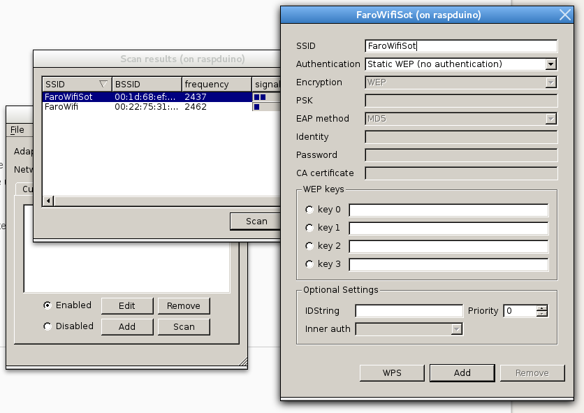
After configuration of your wifi network, command a 'sudo reboot’ from the SSH console and, immediately after the SSH session is closed, remove the ethernet cable.
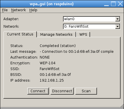
If everything is ok, you will receive an e-mail informing of the new IP, and this IP has been obtained using the wifi USB key.
Now, probably, the IP will have been changed. In this specific case we obtained 192.168.1.25 as the IP through wifi.
You can now 'sudo halt’ it, and then you can remove everything except the USB wifi dongle and the RPi power supply. Now you have a very portable Wifi enabled RPi and you will be able to connect to it using the SSH.
Warning about the Rasbperry Pi USB power
Please take note that the RPi MUST be Rev 2 (see http://www.raspberrypi.org/forums/viewtopic.php?f=63&t=48784 for identification).- If it is Rev 2, then the USB can power a normal wifi USB adapter without problems (check http://raspberrypi.stackexchange.com/questions/9221/highest-current-raspberry-pi-can-take-from-usb, my USB adapter is D-Link DLW-G122 and the currents are Tx 220 mA and Rx 160 mA as seen on http://www.dlink.com/-/media/Consumer_Products/DWL/DWL%20G122/manual/DWLG122_Manual_v3_00_EN_UK.pdf).
- If it is not Rev 2, then probably the USB ports are limited to a recommended max value of 100 mA, as can be checked here: http://raspberrypi.stackexchange.com/questions/340/how-much-power-can-be-provided-through-usb).
You should also check that the RPi power supply used is able to give high current (f.i. 1A or greater) in order to make the wifi dongle to work without interfering the correct RPi behaviour.
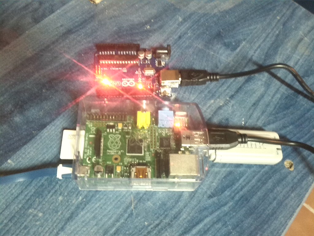
Connecting an Arduino Uno R3 board to the USB port of the RPi.
The RPi can be a fantastic platform to develop & compile Arduino programs. The only thing you need is to connect the Arduino board to the RPi using an USB cable and installing the Arduino IDE toolkit in the RPi.
Please take into account that maximum current at the RPi Power Supply (Rev 2) will be 1.1A and maximum current at the USB connector of the Arduino is limited to 500 mA. For an starting point we can simply connect the Arduino Uno R3 board to the RPi, but if you need extra devices (leds, etc...) you should need to power the Arduino board using the alternative DC power connector, in order to do not use the USB power coming from the RPi.
Check http://arduino.cc/en/Main/arduinoBoardUno, section “USB overcurrent protection”:
USB Overcurrent Protection
The Arduino Uno has a resettable polyfuse that protects your computer’s USB ports from shorts and overcurrent. Although most computers provide their own internal protection, the fuse provides an extra layer of protection. If more than 500 mA is applied to the USB port, the fuse will automatically break the connection until the short or overload is removed.
Now we will make the simplest possible connection:
- 'sudo halt’ to stop the RPi.
- Plug the Arduino UNO R3 using an USB cable to a RPi USB port.
- restart the RPi and connect to it using SSH (don’t forget the -X option).
Installing the arduino tools.
Now we will install the Arduino IDE to the RPi using these instructions:
sudo apt-get install arduino
Once it is installed, we can execute it:
arduino &
And, when asked, select ~/sketchbook as the sketch directory.
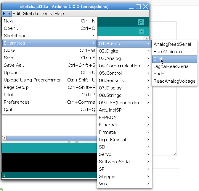
Arduino IDE is showing an empty project, we can test the installation selecting a simple example, compile it, and upload it into the Arduino Uno R3 board.
- Select the menu option File->Examples->Basics->Blink.
- On the new window showing the Blink example source code, check Arduino IDE’s lower right corner to see “Arduino Uno on COM1” or similar message.
- If the message is not present, check cables and the Tools→Board and Tools→Serial Port menu options.
- Let’s compile it using the “Verify” button (or Sketch→Verify/Compile or Ctrl+R).
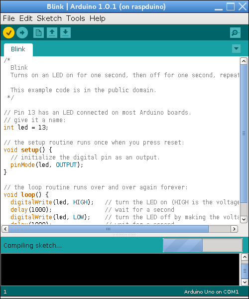
- After a while compiling you will be informed of the binary sketch size.
- Use the “Upload” button to send the binary to the Arduino Uno R3 tool and see it begins to work.
Now we will test the serial console connection with an Arduino.
- Select the menu option File→Examples→Basics→DigitalReadSerial. Repeat same steps than before to compile & upload the code.
- Open Tools → Serial Monitor to see the messages coming from the Arduino.