Support #247

Crear proyecto en uCANca
Description
Crear un proyecto en uCANca para dar soporte al proyecto (y crear sinergia con el desarrollo de uCANca.
MCU_base.ods (133 KB)
uCANca_TGRMach_Arch_Spec.ods (144 KB)
BloquesHw.png View (85.9 KB)
PinoutTeensy.png View (92.6 KB)


History
#1
 Updated by Txinto Vaz about 8 years ago
- File MCU_base.ods added
- File uCANca_TGRMach_Arch_Spec.ods added
- Status changed from New to In Progress
Creamos la hoja de cálculo de arquitectura uCANca Arch, con los siguientes módulos:
- USB: conector USB que nos conecta con un ordenador.
- POW: Toma las corrientes de los diferentes pines del DB9 que puedan llevarlas, y también del pin VUSB que viene del USB, y crea la corriente Vin para la MCU.
- DB9: Conector DB9 de la norma Atari, con entradas viniendo de la MCU (Teensy) y con salidas de voltaje +5V para el módulo POW.
- MCU: Placa de control Teensy.
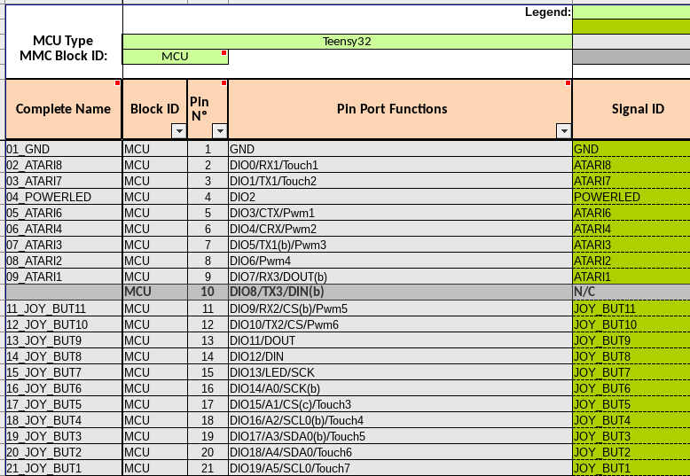
También hemos creado el apartado Teensy32 para definir el pinout de una Teensy 3.2, en el fichero MCU_base.ods
Hemos importado el fichero a un proyecto vacío llamado TGRMach.
El resultado puede verse aquí:
#2
Updated by Txinto Vaz about 8 years ago
Creamos también las funciones:
- Joystick USB.
- Joystick MSX.
- Joystick Amiga.
que se apoyan en las siguientes subfunciones.
- Power USB.
- Power MSX.
- Power Amiga.
- Power Manager.
- USB Encoder.
- MSX Encoder.
- Amiga Encoder.
#3
Updated by Txinto Vaz about 8 years ago
- File BloquesHw.png View added
- File PinoutTeensy.png View added
Podemos ver cómo hemos hecho el pinout en la hoja de cálculo:
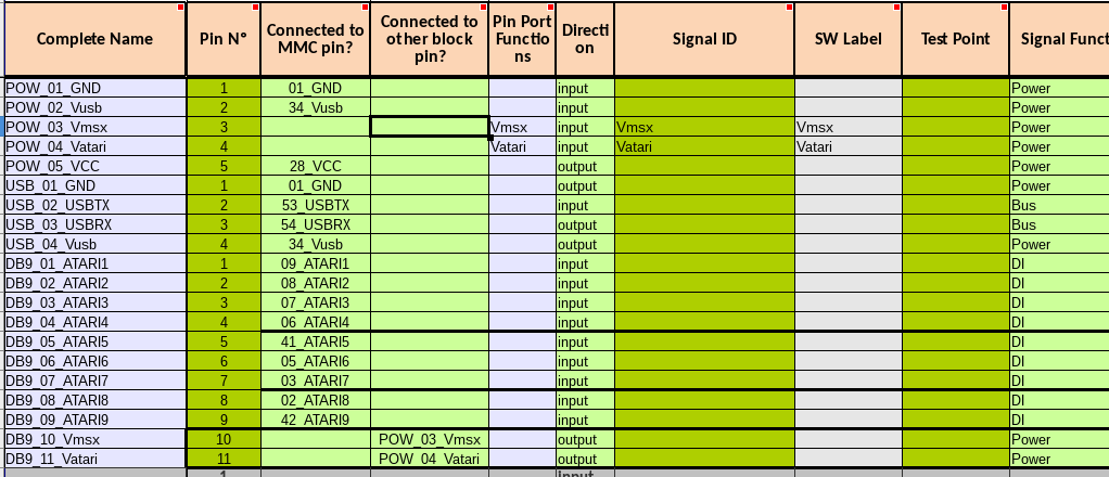
y cómo hemos definido los bloques:
#4
Updated by Txinto Vaz about 8 years ago
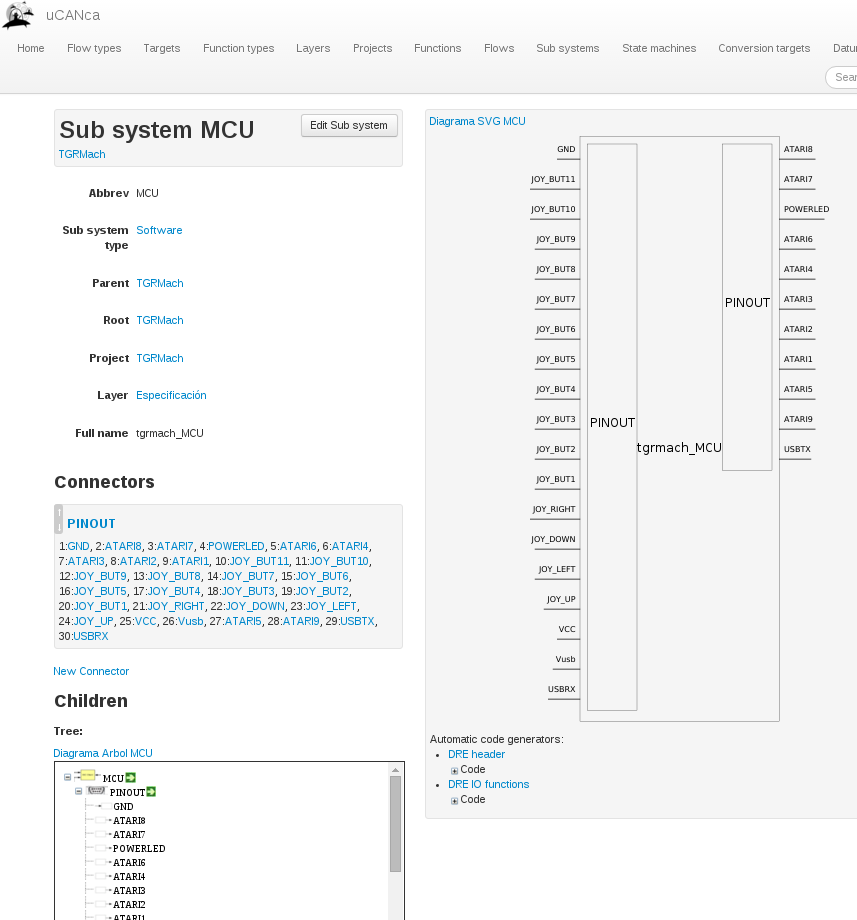
Para ver cómo queda en uCANca, podemos ver el bloque MCU (que representa la Teensy):
#5
Updated by Txinto Vaz about 8 years ago
Recableamos según nueva configuración de pines, ver diferencias en e5584f46
Nuevos pines:
/**** Pin assigment section ****/
#define CFG_POWERGND_PIN 2 // anteriormente 2

#define CFG_JOY_UP_PIN 23 // anteriormente 23
#define CFG_JOY_DOWN_PIN 21 // anteriormente 21
#define CFG_JOY_LEFT_PIN 22 // anteriormente 22
#define CFG_JOY_RIGHT_PIN 20 // anteriormente 20

#define CFG_JOY_GREENBUT_PIN 19// anteriormente 19
#define CFG_JOY_REDBUT_PIN 18 // anteriormente 18
#define CFG_JOY_BLUEBUT_PIN 17 // anteriormente 17
#define CFG_JOY_YELLOWBUT_PIN 16 // anteriormente 16
#define CFG_JOY_GREYBUT_PIN 15 // anteriormente 15
#define CFG_JOY_BLACKBUT_PIN 14 // anteriormente 14
#define CFG_JOY_WHITELBUT_PIN 29 // anteriormente 12
#define CFG_JOY_WHITERBUT_PIN 30 // anteriormente 11
#define CFG_JOY_MODEBUT_PIN 31 // anteriormente 10
#define CFG_JOY_RESTARTBUT_PIN 32 // anteriormente 9
#define CFG_JOY_PLAYERBUT_PIN 33 // anteriormente 8

/**** ATARI norm output ****/
#define CFG_ATARI_PIN_1 9 // anteriormente 7  // MSX FW // AZUL 1er conector
#define CFG_ATARI_PIN_2 8 // anteriormente 6  // MSX BACK // VERDE 1er conector
#define CFG_ATARI_PIN_3 7 // anteriormente 5  // MSX LEFT // AMARILLO 1er conector
#define CFG_ATARI_PIN_4 6 // anteriormente 4  // MSX RIGHT // BLANCO 1er conector
#define CFG_ATARI_PIN_5 5 // anteriormente NC // MSX +5v // ROJO 1er conector
#define CFG_ATARI_PIN_6 12 // anteriormente 3  // MSX TRG1 // AZUL 2o conector
#define CFG_ATARI_PIN_7 11 // anteriormente 1  // MSX TRG2 // VERDE 2o conector
#define CFG_ATARI_PIN_8 10 // anteriormente 0  // MSX OUT // AMARILLO 2o conector
#define CFG_ATARI_PIN_9 4 // anteriormente NC // MSX GND // NEGRO 1er conector
#define CFG_ATARI_PIN_9 4 // anteriormente NC // MSX GND // NEGRO 1er conector